Project 01 · 2026
Rocky.
A self-built 3D-printed quadruped. Twelve servos, an ESP32, and a Jetson Orin Nano running ROS2. Built together with Chris.
At a glance
- Role
- Co-built with Chris - hardware, firmware, software
- Year
- 2026
- Mechanics
- 3D-printed body and legs, 12 servos (3 per leg)
- Compute
- NVIDIA Jetson Orin Nano + ESP32 (currently 2× Arduino Uno)
- Software
- ROS2, Python, C++
- Status
- v1 assembled - walks straight, mechanical and power revisions in progress
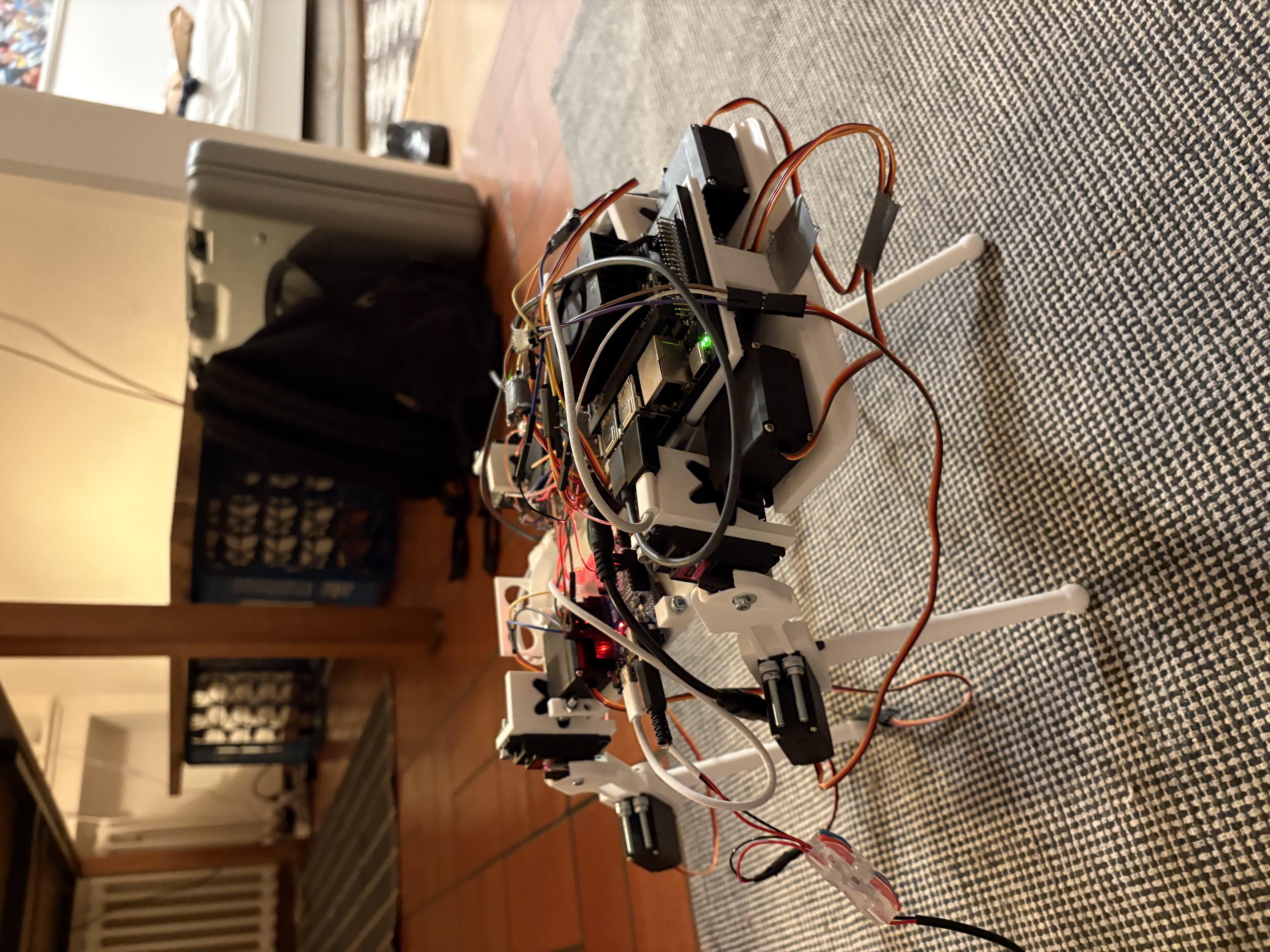
What it is
What Rocky is.
Rocky is a self-built 3D-printed quadruped Chris and I are working on. The idea was to use twelve servos split across four legs, giving three degrees of freedom per leg: outward rotation of the leg (yaw), pitch at the thigh, and rotation at the knee.
The servos are driven by an ESP32, which receives its commands over serial from a Jetson Orin Nano. The Jetson lives in the body and is powered by an onboard battery, so the whole thing is meant to run as a fully autonomous system.
The end goal is to run a local vision model on the Jetson, something like YOLO, and let Rocky navigate around my flat: find and walk to the nearest person, bottle, or whatever else gets asked of it. The same long-term direction as Jeff, just on legs instead of wheels.
Rocky v1
The first build.
Software
ROS2 nodes.
We split the control stack across four ROS2 nodes, each responsible for one step of the pipeline from a desired velocity to a servo command.
- gait_controller - takes a target velocity and publishes the foot positions needed to achieve it. It emits x and z for each foot: x along Rocky's looking direction, z as height.
- inverse_kinematics - turns those four foot positions into per-servo angles relative to the body. For now it only drives the thigh and knee joints; the hip yaw stays fixed.
- angle_mapper - converts the raw kinematic angles into the actual angles each physical servo needs to take, accounting for mounting offsets and direction.
- serial_bridge - ships the final commands over serial to the microcontroller.
With this stack in place, the robot can walk straight on the code side.
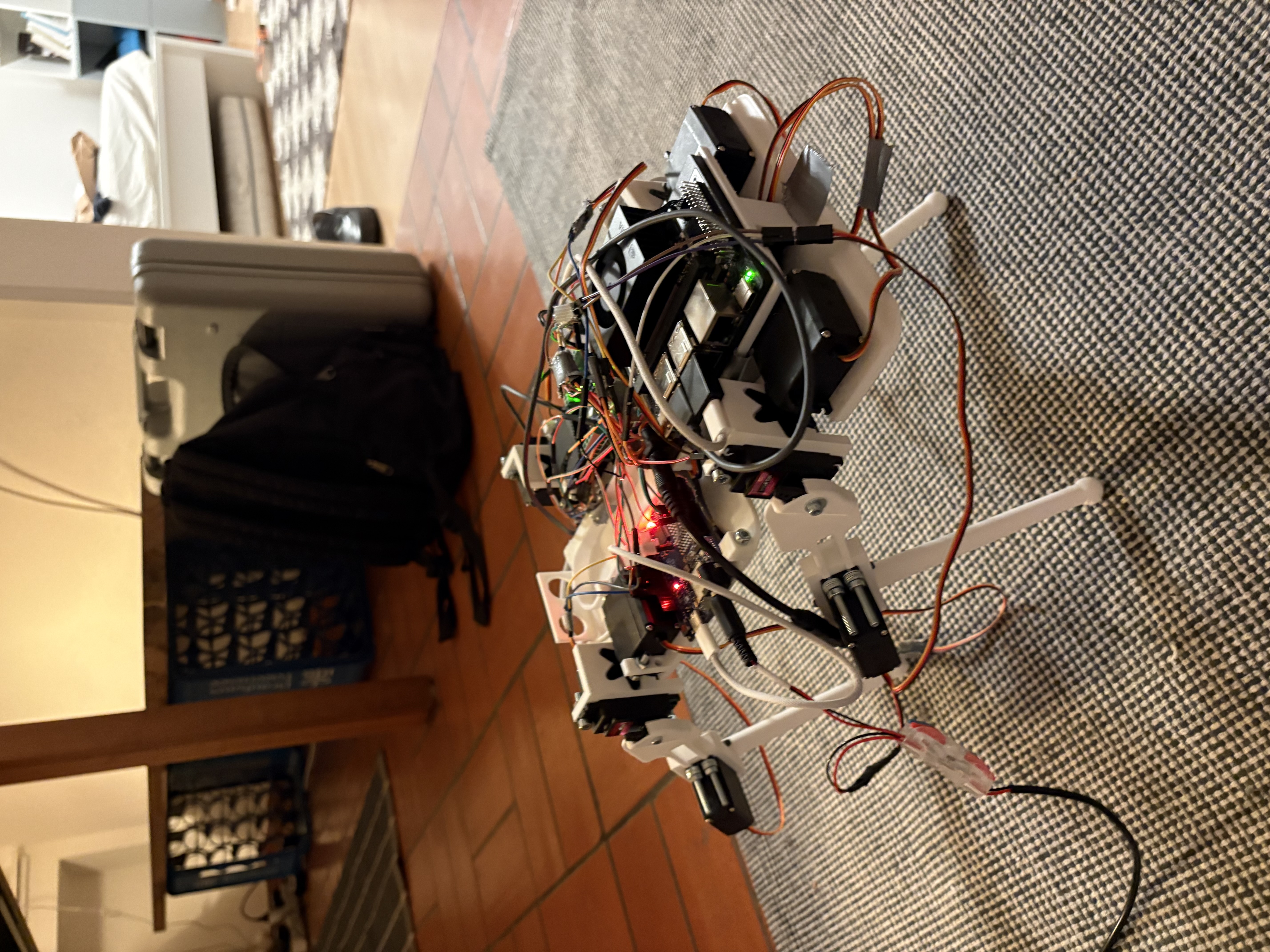
Problems
Where the mechanical side bites back.
The mechanical side isn't as far along as the code. We hit two real problems.
Power. When we planned the robot and ordered parts, we didn't draw an electrical sketch of what connects to what, a mistake I won't repeat. Both batteries run at 12V, but the servos want 5-7V. Without a buck converter we couldn't power the servos directly from the battery, and we couldn't run the ESP either.
The stop-gap was to drive the servos from two Arduino Unos, four each, and to drop the hip-yaw servos for now. One Uno can barely supply four servos at once: as soon as a joint sees any load, the current sags and the joint goes weak. The unpowered yaw servos can't hold position either. In short: the joints we do drive are too weak, and the rest aren't driven at all. The fix is straightforward, a 12V to 5V buck converter to power the servos and the ESP properly.
Mechanics. Most parts aren't stable enough. The feet are too thin, the stance area is too small, and the legs flex under the combined weight of the Jetson, twelve large servos, and two battery packs. All of it is fixable in CAD and another print pass, but it made clear we underestimated the loads once everything was assembled.
Next
CRATER - Mars rover drill