Project 01 · 2025–2026
CRATER - Mars rover drill.
Drill subsystem for TERBY, the rover of ETH Zürich's first rover team, entered in the European Rover Challenge 2026.
At a glance
- Role
- Drill mechanics, small sub-team
- Team
- CRATER, ETH Zürich
- Year
- 2025 – 2026
- Competition
- European Rover Challenge 2026
- Rover / drone
- TERBY / JEZERO
- Task
- Drill 35 cm into sand, extract ≥ 100 g sample
Context
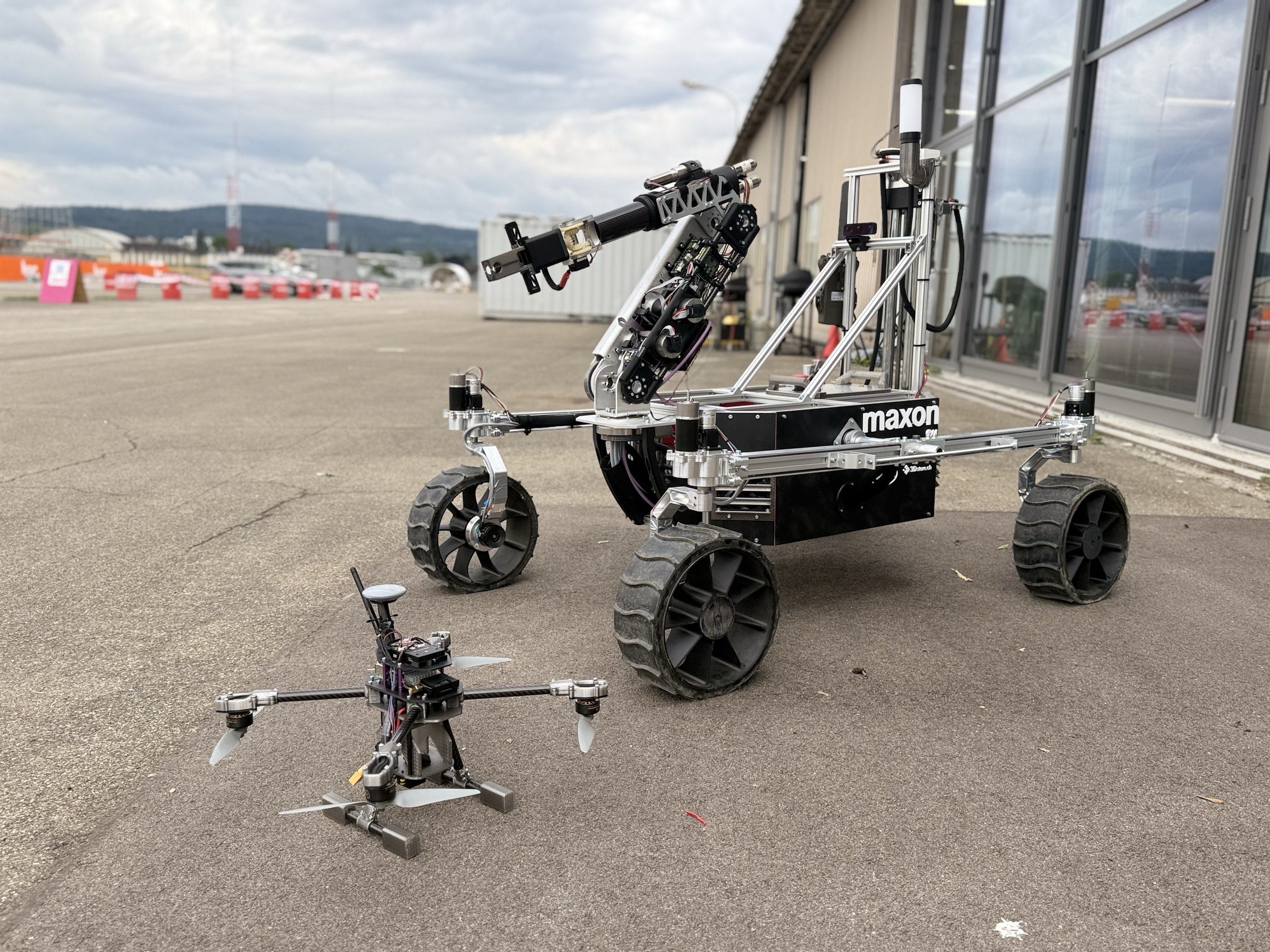
What is CRATER.
CRATER is ETH Zürich's first ever rover team. We are competing in the European Rover Challenge 2026 in September, with the rover TERBY and a companion drone, JEZERO.
The rover has to perform a number of tasks, one of which is a drilling task. The goal is to drill 35 centimeters deep in a sandy environment and extract a sample of at least 100 grams of sand.
System
Introducing the drilling system.
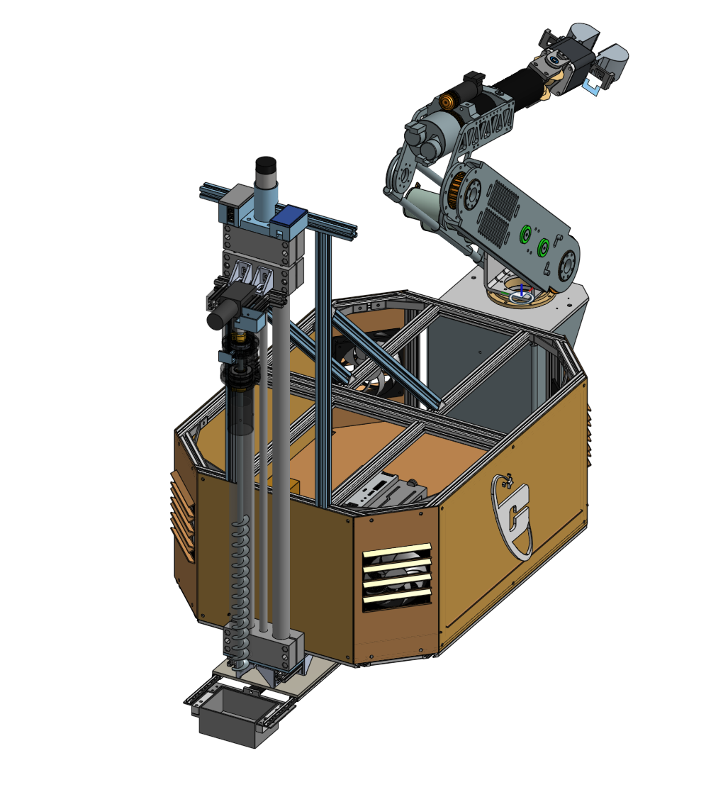
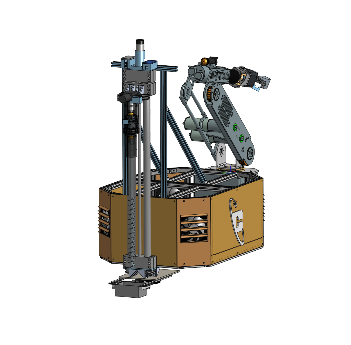
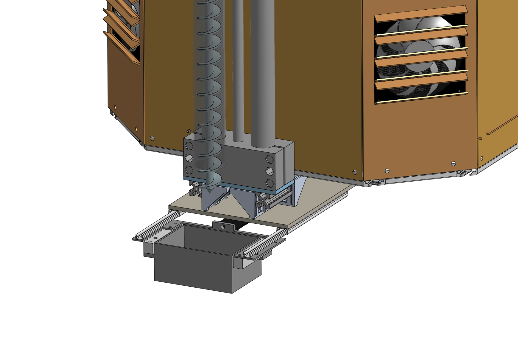
Our drilling system consists of two main parts: the drill itself and a sample container to hold the drilled sand.
For the drill, we use a 70-centimeter-long ground auger with a diameter of 30 millimeters. It sits inside a carbon tube, which prevents sand loss while drilling. The drill is powered by a motor and gearbox, and rotates while being pushed down by a spindle-driven linear unit. Our motors run on 12 V, so we use a DC buck converter to step the rover's 24 V supply down. We chose 12 V motors for weight and accessibility — the extra converter is worth it, also from a weight perspective. While drilling, the auger transports the sand upward into the tube. Once the target depth is reached, the drill is pulled back up.
The second part is the sample container. It moves out on a linear rail until it sits underneath the drill. The drill rotation is then reversed, so that the collected sand falls into the container. The container is finally retracted and safely stored underneath the rover chassis.
Design
CAD overview.
Software
Electronics and software.
Our drilling system connects to the rover via a CAN cable. The rover runs on a Jetson and uses ROS 2.
The drill's own logic runs on an ESP32, which controls two motors through one motor controller each, a light sensor, and an ultrasonic distance sensor. The light sensor acts as an encoder to track the spin rate of the drill.
A second ESP32 handles the sample container. It is not directly connected to the drill, it runs as a separate system, also communicating over CAN.
My role
My responsibilities.
My responsibilities focus on the mechanical side of the drill. Among others, this includes the CAD and printing of parts of the spinning system and the casing of the drill, as well as shortening the drill bit and removing parts of the helix.
Next steps
Next steps.
We will improve the system further by making it lighter. The rover has a weight limit to reach, and we aim to make the drill approximately 2 kg lighter by replacing the off-the-rack linear unit with our own parts — for example using carbon tubes for the linear unit and printing our own sliders.
Next
Jeff - autonomous robot